{{FULL_COURSE}} Homework 6 - Half-Edge Mesh
Overview
-----
You will build upon your knowledge of C++ and OpenGL by creating a half-edge
data structure from interlinked pointers and then visualize your mesh using
OpenGL vertex buffers. This assignment will be the first in creating
a mesh editor application in the style of Autodesk Maya or Blender.
Supplied Code
---------
Click here to access
the homework's Github repository.
Conceptual Questions (10 points, Due Friday, October 18 at 11:59 PM)
-------------
* (5 pts) Given a mesh with all of its half-edges created but none of its SYM
pointers set, what is the minimum information needed to determine which
half-edge should be the SYM of some other half-edge?
* (5 pts) Which function in the `Drawable` class determines the primitives
(i.e. triangles, lines, or points) with which a given mesh will be drawn?
What does `Drawable::getIndexBufferLength` return, and where is this value used?
Help Log (5 points)
-------
Maintain a log of all help you receive and resources you use. Make sure the date
and time, the names of everyone you work with or get help from, and every URL
you use, except as noted in the collaboration policy. Also briefly log your
question, bug or the topic you were looking up/discussing. Ideally, you should
also the answer to your question or solution to your bug. This will help you
learn and provide a useful reference for future assignments and exams. This also
helps us know if there is a topic that people are finding difficult.
If you did not use external resources or otherwise receive help, please submit
a help log that states you did not receive external help.
You may submit your help log as an ASCII (plain) text file or as a PDF. Refer
to the Policies section of the course web site for more specifications.
Code Requirements (Due Wednesday, October 23 at 11:59 PM)
-------
This homework has several main components:
* Half-edge mesh construction
* Mesh topology editing operations
* Creating a GUI to display and deform your mesh components
* Using OpenGL to visualize your mesh and the individual mesh components
For the most part, they are independent of one another, so don't feel as though
you need to complete each item in the order they are listed below.
### Mesh component classes (15 points) ###
You will write three classes to form your half-edge data structure: `Face`,
`HalfEdge`, and `Vertex`. You should follow the format of the half-edge data
structure, as outlined below.
The `Vertex` class should contain variables for the following information:
* A `vec3` for storing its position
* A pointer to one of the `HalfEdge`s that points to this `Vertex`
* A unique integer to identify the `Vertex` in menus and while debugging
The `Face` class should contain variables for the following information:
* A pointer to one of the `HalfEdge`s that lies on this `Face`
* A `vec3` to represent this `Face`'s color as an RGB value
* A unique integer to identify the `Face` in menus and while debugging
The `HalfEdge` class should contain variables for the following information:
* A pointer to the next `HalfEdge` in the loop of `HalfEdge`s that lie on
this `HalfEdge`'s `Face`
* A pointer to the `HalfEdge` that lies parallel to this `HalfEdge` and which
travels in the opposite direction and is part of an adjacent `Face`, i.e.
this `HalfEdge`'s symmetrical `HalfEdge`
* A pointer to the `Face` on which this `HalfEdge` lies
* A pointer to the `Vertex` between this `HalfEdge` and its next `HalfEdge`
* A unique integer to identify the `HalfEdge` in menus and while debugging
You might consider using a static member variable in each of your mesh component
classes that tracks the last ID assigned to a component, and increments that
value by one each time a new vertex/face/half-edge is created. This way you can
assign a copy of the value stored in that variable to the next component you
create and have an easy way of making sure the ID is unique.
### Mesh Class (25 points) ###
You will also create a `Mesh` class to store your `Face`s, `HalfEdge`s, and `Vertex`es.
You should store them in `std::vector`s of `unique_ptr`s. Remember that you can call
the `get()` function of a unique pointer to get a raw pointer that points to the same
memory address, but does not own it. This will be useful when setting the pointer
member variables of each mesh component.
Your `Mesh` class should inherit from `Drawable` so that you can
easily draw it. You'll have to implement `Drawable::initializeAndBufferGeometryData()` so that it can
handle setting up the VBOs for any arbitrary mesh. Your mesh should use the
`GL_TRIANGLES` enum when being drawn, i.e. its `drawMode` function should return `GL_TRIANGLES`,
which means you will have to set up
triangular indices for any half-edge polygon face's index buffer.
You should write `initializeAndBufferGeometryData()` so that it organizes VBO data on a per-face basis
to make determining your face indices easier. In other words, if two faces share
a vertex, there should be duplicate positions in your position VBO for that vertex.
The same goes for surface normals and vertex colors. It
might also be helpful to know that you can pass a `std::vector` as an argument
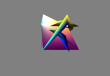
for `glBufferData` by calling its `data()` function. __Your VBO data
should all be stored as `vec3`s since both shaders expect their `in` variables as `vec3`s.__
If your cube mesh looks like this, you probably used `vec4`s for your VBO data instead of `vec3`s:
### OBJ file importing (25 points) ###
Add a button to your GUI that opens a `QFileDialog` that allows the user to
select an OBJ file to be read. Your program should generate a half-edge data
structure from the input file and then render the resulting mesh using VBOs,
wherein each `Face` is assigned a random color. You will only be required to
handle closed and manifold meshes, but you should be able to handle faces with
any number of edges (i.e. n-gons) without triangulating them within your
half-edge mesh structure. You may have your OBJ mesh, once built, replace any
previously existing mesh such as a previously loaded OBJ mesh. If you are unfamiliar with the OBJ file
format, we recommend you read the [Wikipedia article](https://en.wikipedia.org/wiki/Wavefront_.obj_file) describing their formatting
(it is fairly straightforward). When loading an OBJ file, you only need to store
its vertex position information for building your faces. You may choose to only
support OBJ files that follow the face format of `position/uv/normal` (as
opposed to `face//normal` or `face/uv`). This is the format of all the OBJ
files we have provided. If you can load the supplied cow OBJ file within 3
seconds, you've done well!
An important feature some people may forget is to set up is all of the SYM
pointers for the `HalfEdge`s. They are not needed to draw your meshes using
VBOs, but they are vital to performing mesh operations. Make sure you've
properly created your SYM pointers (you can visually test them using the
debugging features you implemented in the previous assignment).
### Graphical User Interface (20 points) ###
Write a simple Qt interface to select the mesh components. We have placed in
your GUI three different `QListWidget`s with which to view and select your
vertices, half-edges, and faces. Allow the user to select a `Vertex`, `HalfEdge`,
or `Face` by clicking on a component in the respective `QListWidget`.
In order to store your mesh components in these lists, you'll have to make them
inherit from the `QListWidgetItem` class, much like your `Node` class inherited
from the `QTreeWidgetItem` class in the scene graph assignment.
When you've selected a face/half-edge/vertex in one of your lists, there should be visual indication of this selection in your GL window:
* A selected `HalfEdge` should be represented as a single `GL_LINES`. The line
should gradiate from red to yellow, with the yellow end corresponding to the
`Vertex` to which the `HalfEdge` points.
* A selected `Vertex` should be represented as a white `GL_POINTS`.
* A selected `Face` should be surrounded by a strip of `GL_LINES` colored with
the opposite color of the `Face`. For example, if a `Face` is red (1,0,0),
then its ring should be cyan (0,1,1).
Additionally, before you draw these mesh components in `paintGL`, you should
invoke `glDisable(GL_DEPTH_TEST)` so that they are always drawn on top of your
mesh's triangles; this makes it easier to find mesh components that are on the
back side of the mesh relative to the camera. However, you should invoke
`glEnable(GL_DEPTH_TEST)` at the end of `paintGL` so that the mesh's triangles
are correctly depth-sorted. We recommend using MyGL's `m_progFlat` shader program
to draw the mesh components, as this does not apply any lighting to the geometry
but instead draws them directly with their base color. This means you won't need
to generate surface normals for these display shapes (not that lines or points
have normals to begin with).
To support highlighting selected components, we recommend that you create three
classes that inherit from `Drawable`, but are separate from your `HalfEdge`,
`Face`, and `Vertex` classes. You should have one "primitive" instance of each
of these `Drawables`, and re-fill their VBOs each time the component type they
represent is selected. For example:
// vertexdisplay.h
class VertexDisplay : public Drawable {
protected:
    Vertex *representedVertex;

public:
    // Creates VBO data to make a visual
    // representation of the currently selected Vertex
    void initializeAndBufferGeometryData() override;
    // Change which Vertex representedVertex points to
    void updateVertex(Vertex*);
};

// mygl.h
class MyGL : public OpenGLContext {
  // Have an instance of VertexDisplay that is
  // drawn in paintGL, and has VBO data representing
  // the position of the currently selected Vertex so
  // it can be drawn as a GL_POINTS
  public VertexDisplay m_vertDisplay;
};
### Visual Debugging Tools (5 points) ###
Add the following key press functionality to your program in order to help
visually debug your half-edge meshes. When the listed key is pressed, the
indicated mesh component should be selected and highlighted:
* `N`: NEXT half-edge of the currently selected half-edge
* `M`: SYM half-edge of the currently selected half-edge
* `F`: FACE of the currently selected half-edge
* `V`: VERTEX of the currently selected half-edge
* `H`: HALF-EDGE of the currently selected vertex
* `Shift + H`: HALF-EDGE of the currently selected face
We recommend storing member variables somewhere in your program (e.g. `MyGL`)
that point to the currently selected vertex/face/half-edge. Don't forget to
initialize these to `nullptr` in the constructor of the class that holds them.
Coding Style (10 points)
-------
To help you write better C++ and GLSL code, we will score each of your homework assignments on three different style elements, which will change from week to week. For this assignment, make sure you:
- Use __raw pointers__ in your mesh component classes to refer to their adjacent components, e.g. a `HalfEdge`'s symmetric `HalfEdge`. It does not make conceptual sense for one mesh component to own the memory of its neighbors.
- Make sure any class member functions you write that do not modify member variables are declared as const functions.
- Leave __no commented-out code__ in your final submission.
Extra Credit (Maximum 20 points)
---------
### Selection via ray casting (15 points) ###
Allow the user to select faces, half-edges, and vertices by clicking on the GL
window. The component nearest to the camera should be the one selected.
The more intersections you implement, the more points you'll be awarded. If you
select a component through ray casting, the GUI list containing that component
should also be updated to reflect your selection.
We recommend treating vertices as small spheres, faces as sets of triangles,
and half-edges as cylinders. To test against half-edges, you might consider
finding the nearest point between the ray and the edge and seeing if that
point's distance from the Half-edge is within some radius.
Submission
--------
We will grade the code you have submitted to Canvas, so make sure you
zip up your entire project! Also make sure to commit all of your files
to Github, and add a comment on your Canvas submission with a link to
your repository.