Classes you will edit:
* Rasterizer
* Polygon
Classes you won't need to edit (but may edit if you so choose)
* Triangle
* Vertex
* MainWindow
* tinyobj
The `Rasterizer` class contains a function named `RenderScene()` that returns a
512x512 `QImage` to be displayed in the GUI. The `QImage` should be constructed
to use the `RGB_32` format. You will have to implement several functions and
classes to properly output a rasterized image. It is important to note that the
features listed below do not necessarily have to be completed in the order they
are written. When you initialize your `QImage`, make sure to populate its pixels
with black using the `fill` function. When you use `QColor`s elsewhere in your
code, you should assign them values using the `qRgb` function, e.g.
`QColor c = qRgb(255, 0, 0);`. Note that `QColors` expect values in the range
[0, 255] rather than [0, 1].
For reference images of expected results, refer to the bottom of this page.
### Convex polygon triangulation (5 points) ###
We have provided you with a `Polygon` class and a function in `MainWindow` that
creates and stores polygons based on an input JSON file. You will have to write
code for the `Polygon` class's `Triangulate()` function that populates the
`Polygon`'s list of `Triangle`s. You may assume that the vertices listed for
`Polygon`s in the input JSON files are always in counter-clockwise order, and
that they always define a convex polygon.
If you wish to test your rendering functionality on triangles without
implementing triangulation, we have provided you with a function that
automatically creates an equilateral triangle Polygon and sets it in the
scene's list of `Polygon`s, bypassing the JSON loading functionality.
You can access this from the Scenes dropdown menu in the GUI.
### Line segments (5 points) ###
Create a class that represents a 2D line segment, to be used when determining
which pixels on a row a triangle overlaps. Each `Segment` instance will represent
one edge of a triangle. It should contain the following member variables:
* Two vectors representing the segment's endpoints. __These vectors should
store their data as floating point numbers, as it is very rare that points
projected into screen space in the projection portion of this assignment
will align exactly with a pixel.__
* __(Optional)__ A variable (or variables) for storing the slope of the line segment. This will
help you to determine which of the three configuration cases the segment falls
into without having to compute the slope more than once. Remember that your
slope should be stored as a float (or floats if you're storing dX and dY).
Your line segment class should also implement the following functions:
* A constructor that takes in both endpoints of the line segment. The
constructor should make use of an initialization list to assign values to __all__
member variables.
* A function that computes the x-intersection of the line segment with a
horizontal line based on the horizontal line's y-coordinate. This function
should return a boolean indicating whether or not the lines intersect at all,
while using a pointer as a function input to write the x-intersection. For
example, `bool getIntersection(int y, float* x) {...}`. This function should
__not__ take in an x-coordinate allocated to the heap, nor should it allocate
heap memory to set the value of x. Refer back to the style guide section on
pointers for more information.
### Bounding boxes (5 points) ###
Create a way to compute and store the 2D axis-aligned bounding box of a
triangle. You will use these bounding boxes to improve the efficiency of
rendering each triangle. Rather than testing every single row of the screen
against a triangle, you will only test the screen rows contained within the
triangle's bounding box. Remember to clamp each bounding box to the screen's
limits.
### Triangle rendering (10 points) ###
The `Rasterizer` class contains a function called `RenderScene()`. Using the
code you wrote for the features listed above, you should be able to draw
triangles on the QImage set up in this function using pixel row overlap.
At this point, you may draw the triangles using a single color for testing.
However, once you complete the next requirement you will be able to draw your
shapes properly with interpolated vertex colors. __If you want your triangles
to render correctly, your iteration over the X coordinates between each
row-edge intersection should store your current X as a float, not an int.
Rounding to an int any time before you write to a pixel will give you incorrect
interpolation values.__
### Barycentric interpolation (10 points) ###
Implement a function that, for a given `Triangle` and point within the `Triangle`,
returns the barycentric influence that each vertex exerts on any attribute
interpolated at the input point. Note that the return value is really three
distinct values, so returning them as a vector is the most straightforward
method.
You will use this interpolation function to properly color the pixels that lie
within a triangle. Each pixel should have a blended color based on the color of
each vertex of the triangle. The weighting of the blending will be determined by
this barycentric interpolation function.
### Z-buffering (5 points) ###
Rather than using the Painter's Algorithm as you did in the previous assignment,
you should sort the Z coordinates of your triangles on a per-fragment basis
rather than a per-triangle basis. We recommend that you create a `std::array` of
floating point numbers in which to store the depth of the fragment that is
currently being used to color a given pixel. Note that it is more efficient to
store this data in a one-dimensional array rather than a two-dimensional array.
If your image is W x H pixels, then your array should contain W \* H elements,
and you can access the element corresponding to `(x, y)` as `array[x + W * y]`.
This type of indexing can be extended to N dimensions, e.g.
`x + W * y + W * H * z` for three dimensions.
Also note that in the 2D scenes we provided, each individual polygon has the same
Z coordinate for each of its vertices, but different polygons have different overall
Z coordinates. We are implementing Z buffering primarily so that when you render
3D shapes, they have appropriate sorting.
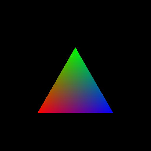
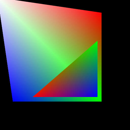
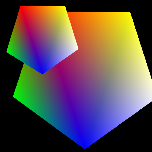
### Testing your implementation so far ###
Once you've implemented all of the features of the 2D triangle rasterizer, you
should be able to render all of the JSON scenes with the `2D_` prefix. Here
are reference images to which you can compare your results. Your results
do not need to match 100%, but they should be similar and have no obvious
errors.
If you encounter dangling pixels or noticeable black lines between triangles,
make sure you are not rounding your edge intersection X coordinate to an integer
value until you are writing your pixel colors to the `QImage`.
| equilateral_triangle.json |
two_polygons.json |
 |
 |
| regular_pentagon.json |
pentagons.json |
 |
 |


